
Components — rotary valves
Rotary valves
and airlocks.
The component every pneumatic system depends on: powder passes down, pressure stays put.
In brief
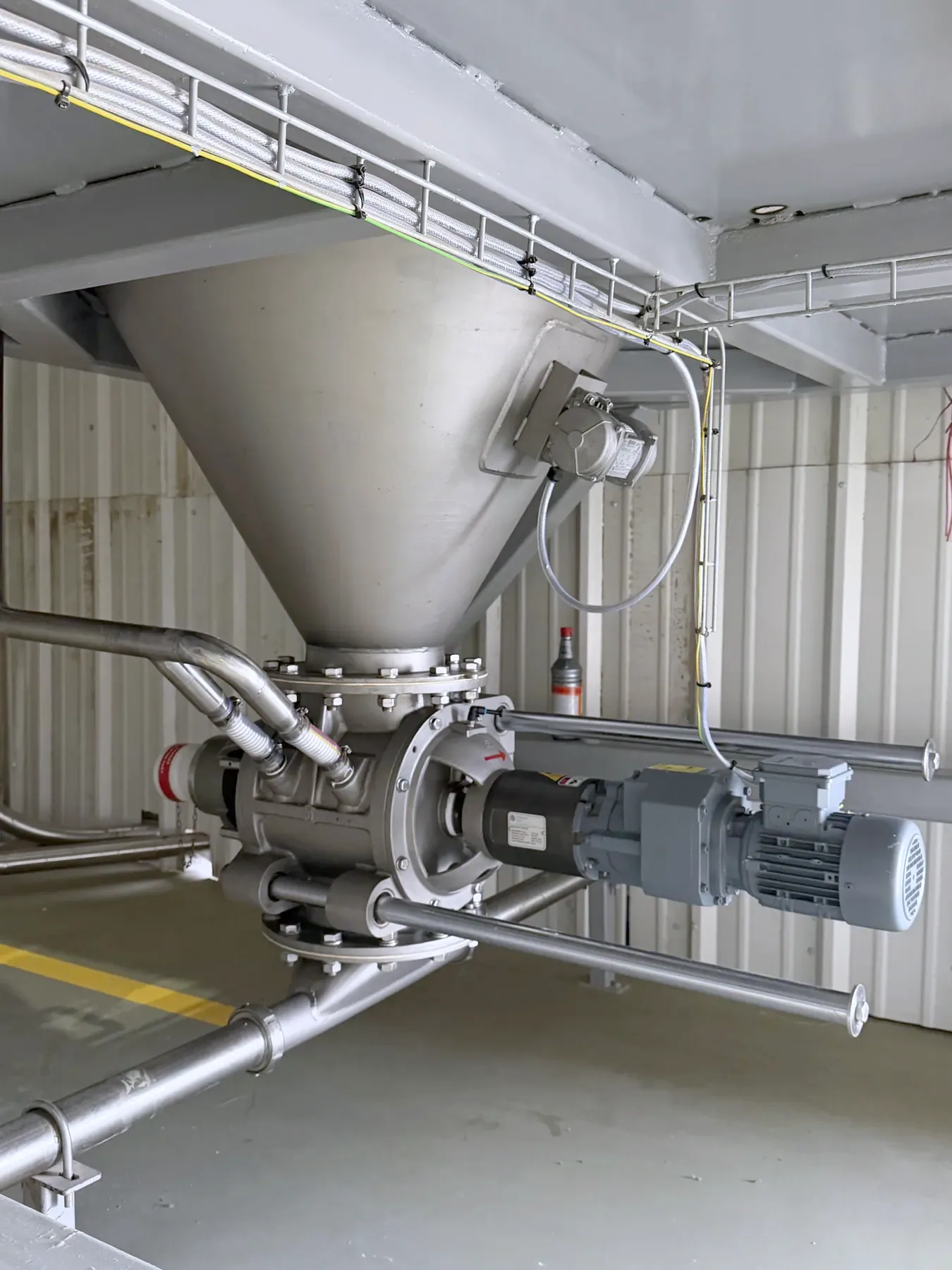
A rotary valve (rotary airlock) meters powder through a multi-vane rotor turning in a close-tolerance housing — material passes from hopper to convey line while the vanes maintain the pressure differential. It is simultaneously the feeder, the airlock and, in classified plants, an ATEX-certified explosion isolation device.
In detail
How it works.
Every pocket of the rotor carries a measured volume, so valve speed is feed rate — the metering device and the airlock in one casting. Tolerances decide performance: leakage air rises sharply with wear, which is why quality valves are machined, not just cast.
In dust-zoned plants a certified rotary valve doubles as explosion isolation, preventing flame propagation between vessels — one of the quiet reasons component quality matters to compliance, not just uptime.
- Duties
- Convey-line feeding · hopper discharge metering · airlock
- Formats
- Drop-through and blow-through, cast and fabricated
- Options
- Quick-clean rail-out rotors for hygiene duties
- Compliance
- ATEX-certified explosion isolation variants
Common questions
Frequently asked questions.
- How does a rotary airlock valve work?
- A multi-vane rotor turns inside a machined housing. Each pocket fills with powder at the top inlet, carries it around, and discharges at the bottom — while at every rotor position at least one vane seals inlet from outlet, holding the pressure difference between hopper and convey line.
Related
Related pages.
Discuss your project.
Talk to an engineer.
Send the material, throughput and plant constraints. You’ll get a considered answer from an engineer, not a brochure.